Getting Started with Qucs Analogue Circuit Simulation
Qucs is a scientific/engineering software package for analogue and digital circuit simulation, including linear and non-linear DC analysis, small signal S parameter circuit analysis, time domain transient analysis and VHDL/Verilog digital circuit simulation. This section of the Qucs-Help document introduces readers to the basic steps involved in Qucs analogue circuit simulation. When Qucs is launched for the first time, it creates a directory called .qucs within the user’s home directory. All files involved in Qucs simulations are saved in the .qucs directory or in one of it’s sub-directories. After Qucs has been launched, the software displays a Graphical User Interface window (GUI) similar, or the same, to the one shown in Figure 1.
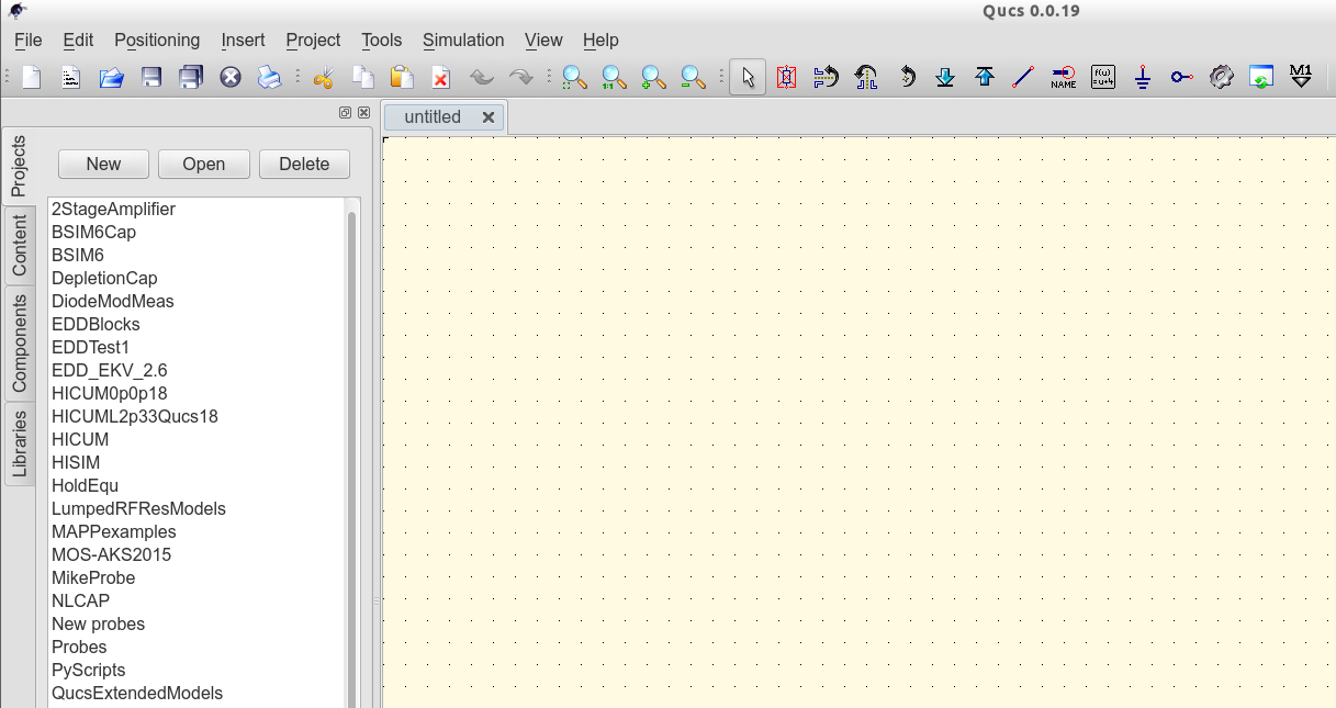
Abbildung 1 - Qucs Hauptfenster
Before using Qucs it is advisable to set the program application settings. This is done from the File  Application Settings menu. Clicking on Application Settings causes the EditQucsProperties window to be displayed, see Figure 2. Complete, with appropriate entries for your Qucs installation, the Settings, Source Code Editor, File Types and Locations menus.
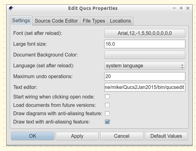
Figure 2 - QucsEditProperties window
On launching Qucs a working area labelled (6) appears at the centre of the GUI. This window is used for displaying schematics, numerical and algebraic model and circuit design data, numerical output data, and signal waveforms and numerial data visualised as graphs, see Figure 3. Clicking, with the left hand mouse button on any of the entries in the tabular bar labelled (5) allows users to quickly switch between the currently open documents. On the left hand side of the Qucs main window is a third area labelled (1) whose content depends on the status of Projects (2), Content (3), Components (4) or Libraries. After running Qucs, the Projects tab is activated. However note, when Qucs is launched for the first time the Projects list is empty.

Figure 3 - Qucs main window with working areas labelled
To enter a new project left click on the New button located on the right above window (1). This action causes a Qucs GUI dialogue to open. Enter the name of a Qucs project in the box provided, for example enter QucsHelpFig and click on the OK button. Qucs then creates a project directory in the ~/.qucs directory. In the example shown in Figure 3 this is called QucsHelpFig_prj. Every file belonging to this new project is saved within the QucsHelpFig_prj directory. On creation a new project is immediately opened and it’s name displayed on the Qucs window title bar. The left tabular bar is then switched to Content, and the content of the currently opened project displayed. To save an open document click on the save button (or use the main menu: File  Save). This step initiates a sequence which saves the document displayed in area (6). To complete the save sequence the program will request the name of your new document. Enter firstSchematic, or some other suitable name, and click on the OK button to complete the save sequence.
As a first example to help you get started with Qucs enter and run the simple DC circuit shown in Figure 3. The circuit illustrated is a two resistor voltage divider network connected to a fixed value DC voltage source. Start by clicking on the Components tab. This action causes a combo box to be displayed from which a component group may be choosen and the required components selected. Choose components group lumped components and click on the first symbol: Resistor. Next move the mouse cursor into area (6). Pressing the right mouse button rotates the Resistor symbol. Similarly, pressing the left mouse button places the component onto the schematic at the place the mouse cursor is pointing at. Repeat this process for all components shown in Figure 3. The independent DC voltage source is located in the sources group. The ground symbol can be found in the lumped components group or selected from the Qucs toolbar. The icon requesting DC simulation is listed in the simulations group. To edit the parameters of the second resistor, double-click on it. A dialogue opens which allows the resistor value to be changed; enter 100 Ohm in the edit field on the right hand side and click enter.
To connect the circuit components shown in Figure 3, click on the wire toolbar button (or use the main menu: Insert Wire). Move the cursor onto an open component port (indicated by a small red circle at the end of a blue wire). Clicking on it starts the wire drawing sequence. Now move the drawing cursor to the end point of a wire (normally this is a second red circle attached to a placed component) and click again. Two components are now connected. Repeat the drawing sequence as many times as required to wire up the example circuit. If you want to change the corner direction of a wire, click on the right mouse button before moving to an end point. You can also end a wire without clicking on an open port or on a wire; just double-click the left mouse button.
As a final step before DC simulation label the node, or nodes, who’s DC voltage is required, for example the wire connecting resistors R1 and R2. Click on the label toolbar button (or use the menu: Insert Wire Label). Now click on the chosen wire. A dialogue opens allowing a node name to be entered. Type divide and click the OK button. If you have drawn the test schematic correctly the entered schematic should look the same, or be similar to, the one shown in Figure 3.
To start DC simulation click on the Simulate toolbar button (or use menu: Simulation Simulate). A simulation window opens and a sliding bar reports simulation progress. Normally, all this happens so fast that you only see a short flickering on the PC display (this depends on the speed of your PC). After finishing a simulation successfully Qucs opens a data display window. This replaces the schematic entry window labelled (6) in Figure 3. Next the Components diagrams toolbar is opened. This allows the simulation results to be listed. Click on the Tabular item and move it to the display working area, placing it by clicking the left hand mouse button. A dialogue opens allowing selection of the named signals you wish to list, see Figure 4. On the left hand side of the Tabular dialogue (called Edit Diagram Properties) is listed the node name: divide.V. Double-click on it and it will be transferred to the right hand side of the dialogue. Leave the dialogue by clicking the OK button. The DC simulation voltage data for node divide should now be listed in a box on the data display window, with a value of 0.666667 volts.
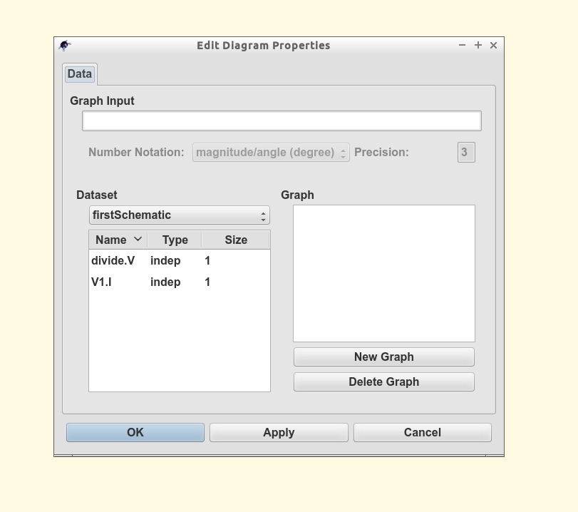
Figure 4 - Qucs data display window showing a Tabular dialogue